Early Silicon Monolithic Integrated Logic Circuits used in the CP-823/U Univac 1830
Monolithic Integrated Circuits
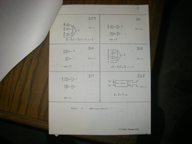
NDRO (Non-Destructive Read Out) Logic Symbols and circuit types. Figure 4 shows the symbols used to represent integrated circuits on the NDRO Thin Film Memory logic diagrams. Only the overall transfer functions (relation of imputs to outputs) are specified for the various integrated circuits. Consequently, a given logic type has no fixed electronic arrangement as long as the proper overall characteristics exist.
All of the logic types except 311 have a maximum fanout of five. Type 311 has a higher power capability and has a maximum fanout of 32. Fanout is not specified for the type 317 since it is used in several different load situations.
Operating potentials for the logic circuits are ground and +4 volts.
Acceptable 0-level signals fall in the range 0-0.75 volts DC. Acceptable 1-level signals are in the range of 2-4 volts DC. Unused inputs are left floating.
Type 317 requires +10 volts and ground. It accepts the standard logic levels and generates in-phase outputs in the range from 0.4 volts (0 volts in) to 7.5 volts (+4 volts in).
Each of the types 309 and 312 contain one logic configuration consisting of a number of interconnected basic elements. The other types contain two separate and unrelated logic groups. Each half can perform a completely different function from its other half.
Type 322 is a monostable multivibrator. The circuit is triggered by a negative going pulse on either pin 8 or pin 9. Output pin 7 produces a negative pulse while output pin 10 provides a positive pulse. A capacitor connected between pins 2 and 3 control the output pulse width. Maximum fanout is 4.
Monolithic Integrated Circuits
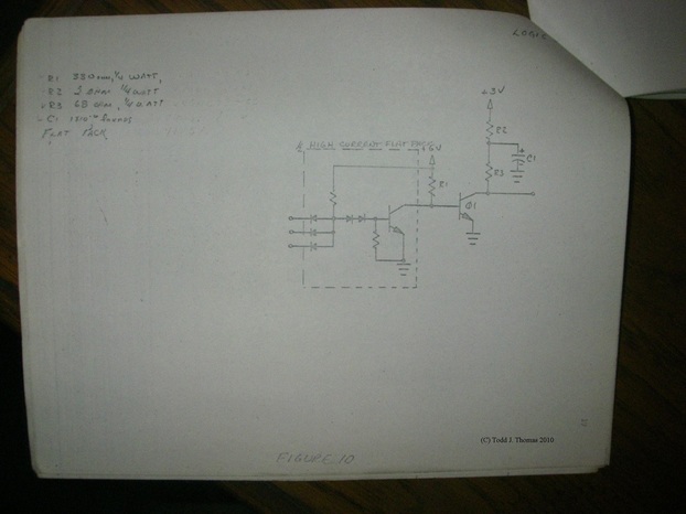
Figure 10 represents a typical dual NAND flat-packaged integrated circuit used on the 90-pin PC cards throughout the CP-823/U computer. Pin 2, 3, 4, 7, 8 and 9 are inputs. Outputs are on pins 1 and 6. Ground is on pin 10 and +6 volts on pin 5. The collector load resistances are external to the circuit. Unused inputs are not connected.
Two NAND inverters can be tied together to form a flip-flop circuit. This is accomplished by connecting the output of each inverter to an input of the other inverter.
The connectors of two or more inverters may be connected to +3 volts through a common load resistor to provide an “OR” function.
Two NAND inverters can be tied together to form a flip-flop circuit. This is accomplished by connecting the output of each inverter to an input of the other inverter.
The connectors of two or more inverters may be connected to +3 volts through a common load resistor to provide an “OR” function.
